Dom / Produkt / Łożysko jdb stałe / JGBF Brass Oilless Ejector Flanged Guide Bearings Bushings
hurtowy JGBF Brass Oilless Ejector Flanged Guide Bearings Bushings

JGBF Brass Oilless Ejector Flanged Guide Bearings Bushings

Opis produktu:

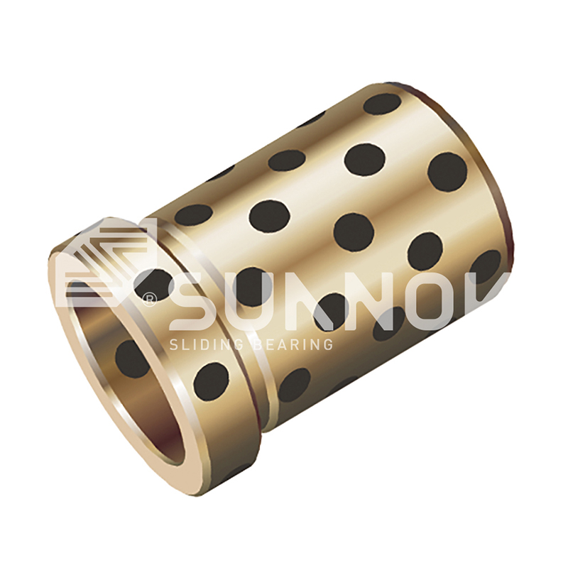
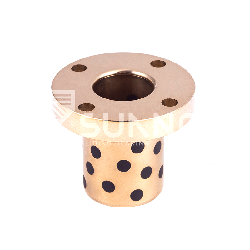
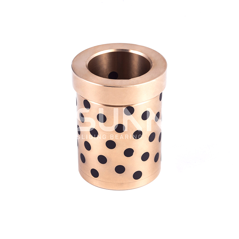
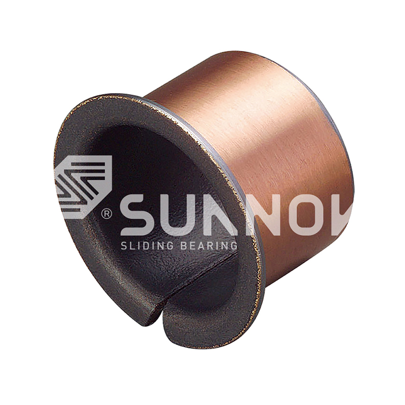
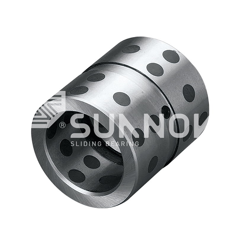
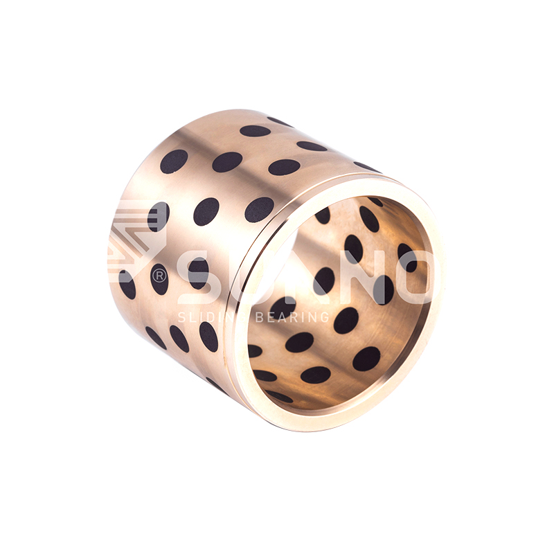
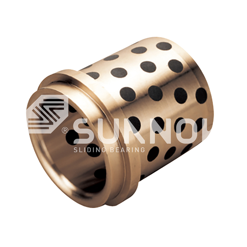
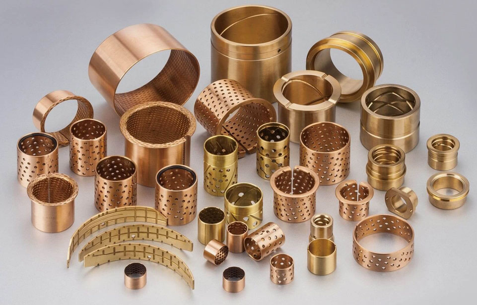
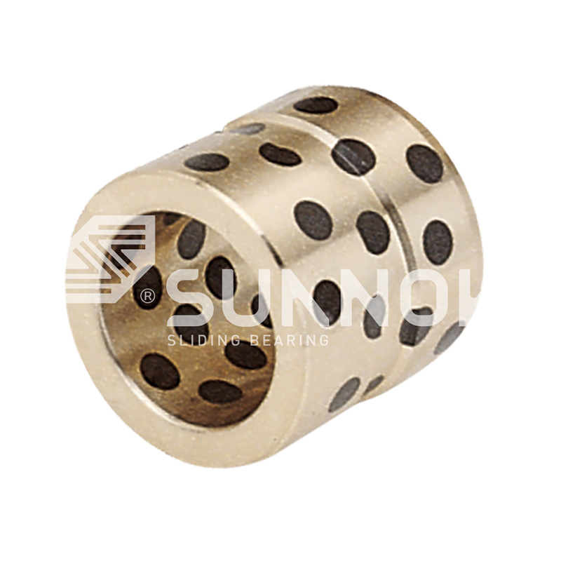
JGBF Brass Oilless Ejector Flanged Guide Bearings Bushings Brass is used as the base material and graphite solid lubricant is embedded in it, which has self-lubricating properties. The bearings have a low friction coefficient (0.05-0.12) and can operate stably under high load and high temperature environments without external lubrication. They have strong wear resistance and long service life. JGBF bearings are corrosion-resistant and suitable for a variety of harsh working conditions. Applications include machinery manufacturing, automobiles, construction, port machinery, agriculture, medical treatment and wind energy, and are widely used in equipment that requires high precision, high load capacity and maintenance-free operation. There are a variety of standard sizes to adapt to a variety of mechanical equipment.

Opis produktu

Standard No. d L d  G6 D  m6 D1 T L1
JGBF-12×19 12  19  12  +0.016
+0.006
18  +0.018
+0.007
25  19 
JGBF-12×24 24
29
24 
JGBF-12×29 29 
JGBF-12×34 34  34 
JGBF-16×19 16  19  16  25  +0.025
+0.009
30  19 
JGBF-16×24 24  24 
JGBF-16×29 29  29 
JGBF-16×34 34  30 
JGBF-16×39 39
49
30 
JGBF-16×49 30 
JGBF-20×24 20  24  20  +0.020
+0.007
30  35  24 
JGBF-20×29 29  29 
JGBF-20×34 34  34 
JGBF-20×39 39  39 
JGBF-20×49 49 40 
JGBF-20×59 59 40 
JGBF-25×24 25  24 25  35  +0.025
+0.009
40  24 
JGBF-25×29 29 29 
JGBF-25X34 34 34 
JGBF-25X39 39  39 
JGBF-25×49 49  49 
JGBF-25×59 59 50 
JGBF-25×69 69 50 
JGBF-30×29 30  29 30  42 47  10  29 
JGBF-30×34 34 34 
JGBF-30×39 39  39 
JGBF-30×49 49  49 
JGBF-30×59 59  59 
JGBF-30×69 69  60 
JGBF-30×79 79  60 
JGBF-35×39 35  39  35


+0.025
+0.009
48 +0.025
+0.009
54  10 39 
JGBF-35×49 49  49 
JGBF-35×59 59  59 
JGBF-35×69 69  69 
JGBF-35×79 79  70 
JGBF-35×89 89  70 
JGBF-35×99 99  70 
JGBF-40×39 40 39  40 55 +0.030
+0.011
61 39 
JGBF-40×49 49  49 
JGBF-40×59 59  59 
JGBF-40×69 69  69 
JGBF-40×79 79  79 
JGBF-40×89 89  80 
JGBF-40×99 99  80 
JGBF-40×109 109  80 
JGBF-50×49 50 49  50 70 76 12 49 
JGBF-50×59 59  59 
JGBF-50×69 69  69 
JGBF-50×79 79  79 
JGBF-50×89 89  89 
JGBF-50×99 99  90 
JGBF-50×109 109  90 
JGBF-50×119 119  90 
JGBF-60×99 60 99  60  +0.029
+0.010
80  86  15  99 
JGBF-60×109 109  109 
JGBF-60×119 119 110 
JGBF-60×129 129  110 
JGBF-60×149 149  110 

Wprowadzenie do produktu

Flanged Ejector Guide Series

JGBF Brass Oilless Ejector Flanged Guide Bearings Bushings

300
°C
Operating Temperature
Flanged
Configuration
Integral Retention
0.18
μ
Friction at 250°C
Flanged Guide Architecture

The JGBF series combines high temperature brass substrate with an integral flange designed specifically for ejector guide applications. The flange provides positive axial location within the mold or die platen, eliminating the need for separate retaining rings or shoulder bolts. This configuration simplifies installation and ensures consistent guide positioning during thermal cycling. Graphite lubricant inserts are distributed across both the cylindrical guide bore and the flange thrust face, providing lubrication for both radial guidance and axial seating contact. The flanged design also facilitates easier removal during maintenance through access from the flange side.

Flange Diameter 1.5x OD standard
Flange Thickness 2.5mm - 5.0mm
Guide Tolerance ISO H8 at 20°C
F
Flange Retention Integral flange eliminates separate hardware, reduces assembly steps
T
Thermal Stability Special brass alloy maintains dimensional accuracy to 300°C
G
Dual Surface Lubrication Graphite on bore and flange face for combined motion lubrication
E
Ejector Pin Guidance Designed specifically for ejector pin stroke and load requirements

Flanged Design Specifications

Flange Face Flatness 0.015mm per 50mm diameter Perpendicular to bore axis
Flange OD Tolerance ISO h11 Standard clearance fit
Flange Corner Radius R1.0mm maximum Prevents stress concentration
Flange Graphite Pattern Radial insert arrangement 8 inserts on flange face

Flanged Guide Applications

  • Injection molding ejector plates with guided pins
  • Die casting ejector systems requiring axial retention
  • Hot stamping tool ejector mechanisms
  • Thermoforming mold ejector guides
  • Compression molding press ejectors
  • Automated transfer die ejector systems

Flange Integration Benefits

  • Self-aligning flange face with counterbore seat
  • Eliminates separate thrust washer components
  • Reduces assembly time by 40% compared to non-flanged
  • Provides visual confirmation of full seating during installation
  • Allows removal using pry tool without damaging housing

Flanged Configuration Comparison

Feature JGBF Flanged Standard Sleeve With Retaining Ring
Axial Retention Method Integral flange Interference fit only Separate ring
Assembly Components 1 1 2
Disassembly Access Flange side Press out from rear Ring removal required
Axial Load Capacity 45 N/mm² 25 N/mm² 35 N/mm²
Thermal Expansion Matching Optimized for steel Standard Ring dependent

Flanged Guide Size Matrix

Guide ID mm OD mm Flange OD mm Length L mm Flange Thick mm Max Pin Speed m/s
6 10 16 12, 16, 20 2.0 0.6
8 12 20 16, 20, 25 2.5 0.6
10 16 26 20, 25, 30 2.5 0.55
12 18 30 25, 30, 40 3.0 0.5
16 24 38 30, 40, 50 3.0 0.45
20 30 48 40, 50, 60 3.5 0.4
25 36 56 50, 60, 80 4.0 0.35
32 44 68 60, 80, 100 4.0 0.35
40 54 82 80, 100, 120 4.5 0.3
50 66 100 100, 120, 150 5.0 0.3
Flange thickness and diameter can be customized for specific mold platen counterbore dimensions.
Installation Sequence
1 Clean counterbore shoulder and bore. Verify depth matches flange thickness.
2 Chamfer counterbore entry at 1.5mm x 15 degrees to prevent flange edge damage.
3 Apply thin lubricant to housing bore only. Do not apply to guide bore.
4 Press using flat tool contacting flange face uniformly. Press until flange seats.
5 Verify flange flushness with housing surface. Tolerance ±0.05mm.
Frequently Asked Questions
Can the flange face handle thrust loads Yes. Flange face supports axial loads up to 45 N/mm². Graphite inserts on flange provide lubrication during axial contact.
What is the recommended counterbore depth Counterbore depth should equal flange thickness plus 0.05mm clearance for thermal expansion at operating temperature.
How to remove a JGBF bearing Use a pry tool between flange edge and housing. Do not pry against the guide bore or graphite inserts.
Flange eccentricity tolerance Flange OD concentricity to guide ID maintained within 0.05mm TIR for standard production.
Flange Surface Finish Ra 0.8 µm
Bore Surface Finish Ra 0.4 µm
Material Grade CuSn8 High Temp
Graphite Coverage 22% bore / 18% flange
Zhejiang Shuangnuo Bearing Technology Co., Ltd.
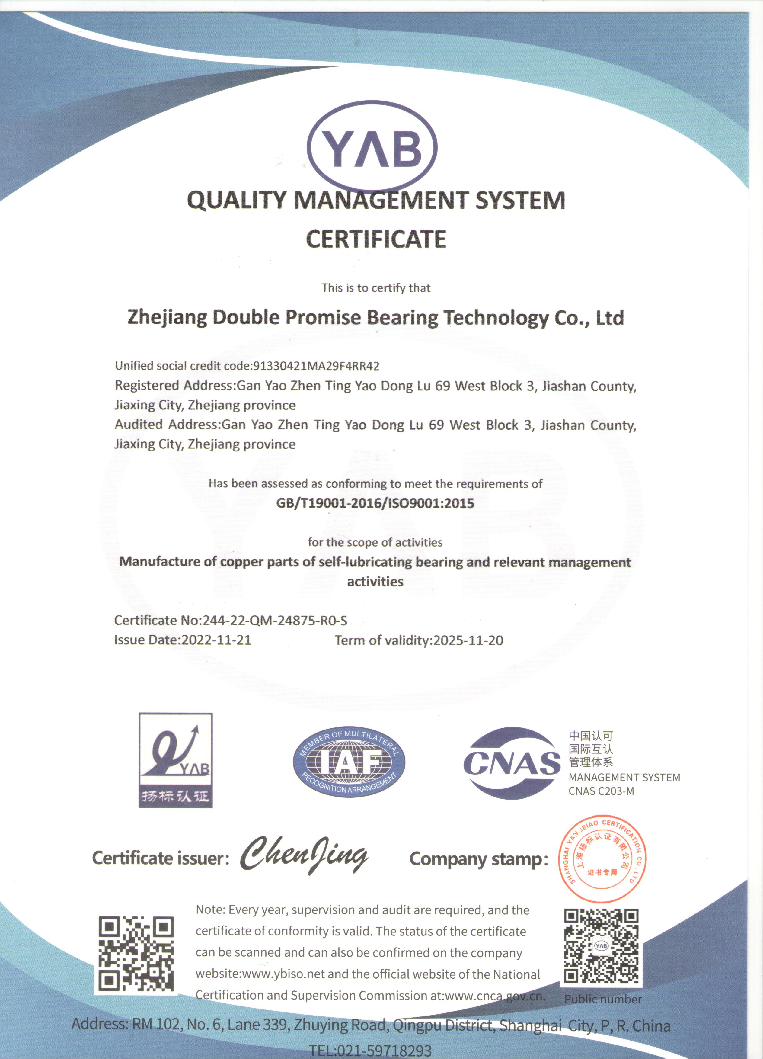
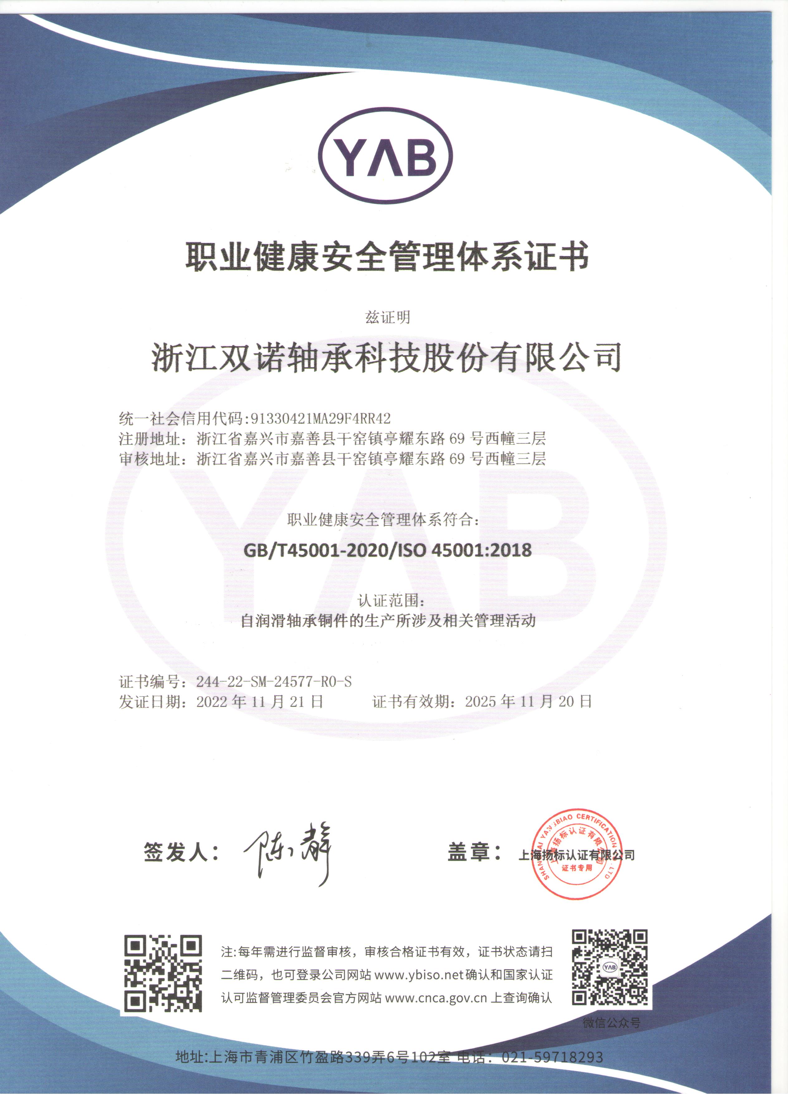
Zhejiang Shuangnuo Bearing Technology Co., Ltd. Tak Chiny JGBF Brass Oilless Ejector Flanged Guide Bearings Bushings dostawca I hurtowy JGBF Brass Oilless Ejector Flanged Guide Bearings Bushings firma, Jesteśmy profesjonalnym producentem różnorodnych samosmarujących produktów ze stopów miedzi, wykorzystującym takie procesy jak odlewanie odśrodkowe, odlewanie ciągłe i odlewanie w formach metalowych. Główne produkty obejmują mosiądz, brąz aluminiowy, brąz cynowy itp. produkowane zgodnie z gatunkami określonymi w normach krajowych. Na tej podstawie przetwarzamy i produkujemy różnorodne produkty łożyskowe samosmarujące, wkładane. Zajmujemy się również produkcją wyrobów bimetalicznych i wielu innych produktów w technologii spiekania. Przez blisko dziesięć lat od momentu założenia firma skupiała się na badaniach, rozwoju i produkcji różnych nowych łożysk samosmarujących.

W procesie produkcji wyrobów firma zawsze kładzie nacisk na niezależne odlewanie i produkcję surowców, aby zagwarantować jakość produktu już od źródła; Proces odlewania jest monitorowany na bieżąco, a gotowe produkty są testowane trzykrotnie spektrometrem przed, w trakcie i po wyjęciu z pieca, aby potwierdzić skład materiałowy produktu. Firma regularnie zleca krajowym instytucjom badawczym testowanie składu materiałowego oraz właściwości mechanicznych swoich produktów i może przedstawić klientom, którzy tego potrzebują, wiarygodne raporty z testów. Firma wdraża zintegrowaną produkcję, od materiału po obróbkę gotowego produktu, i posiada ponad 80 głównych urządzeń, takich jak zaawansowane obrabiarki CNC, tokarki CNC i centra obróbcze. Duża zdolność produkcyjna pozwala na zorganizowanie dostawy materiałów dla klientów w możliwie najkrótszym czasie, co skraca cykl produkcyjny.
  • 0+
    Ustanowienie

    Firma Shuangnuo została założona w 2014 roku i ma 10 lat doświadczenia w branży.

  • 0+
    Zaawansowany sprzęt

    Duże moce produkcyjne pozwalają nam organizować produkcję materiałów dla klientów w możliwie najkrótszym czasie i skracać cykl produkcyjny.
  • 0+
    Satysfakcja Klienta

    Mamy ponad 5000 stałych klientów na całym świecie.

Nasze wiadomości //
Wiadomości i spostrzeżenia.
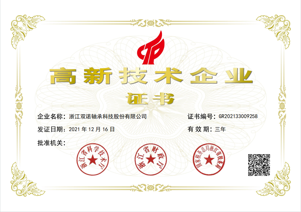
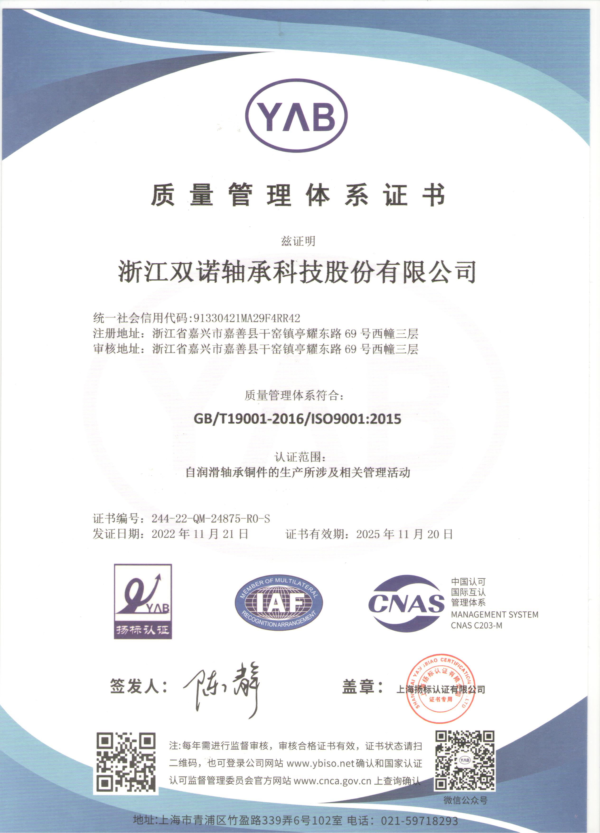
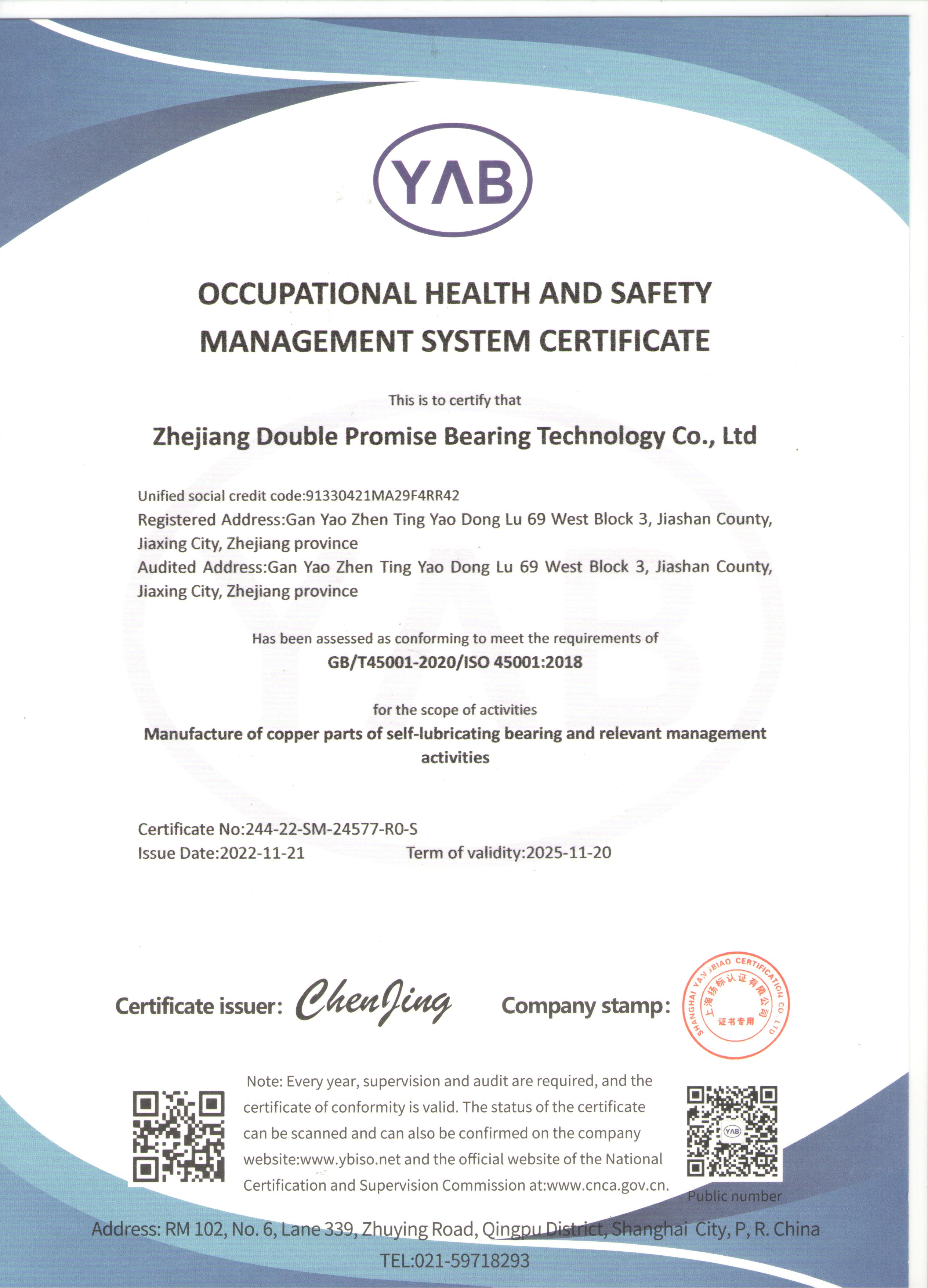
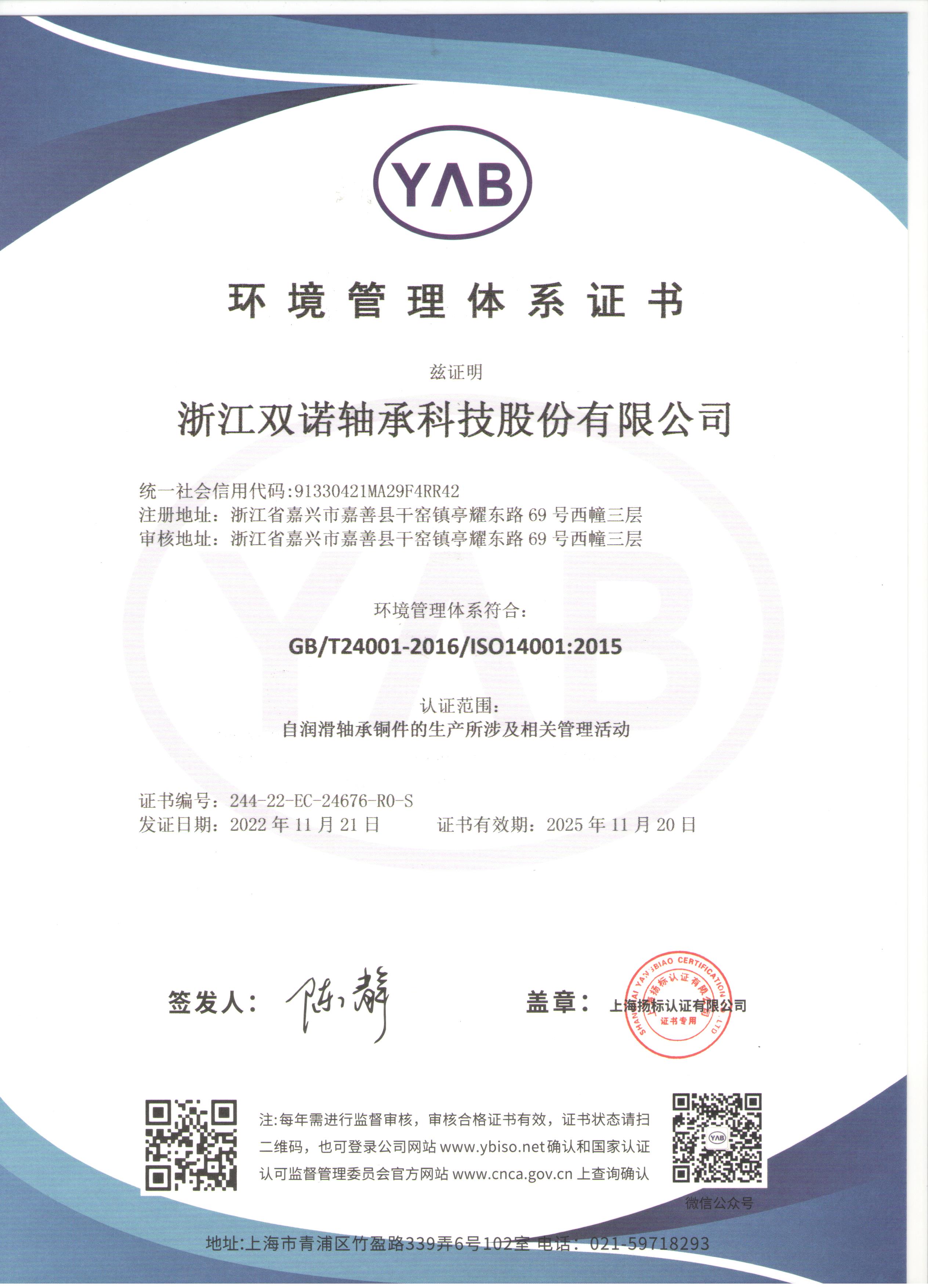
Nasz Honor //
honor.
Zhejiang Shuangnuo Bearing Technology Co., Ltd.
Ścisła kontrola jakości //
Wybierając produkty, skup się na jakości.
Skup się na każdym procesie, aby tworzyć produkty wysokiej jakości.
Zdajemy sobie sprawę, że tylko oferując produkty najwyższej jakości możemy sprostać oczekiwaniom naszych klientów oraz zbudować dobrą reputację i wiarygodność.

Wymagamy, aby samosmarujące produkty ze stopów miedzi spełniały odpowiednie normy i przepisy krajowe. Będziemy ściśle przestrzegać krajowych standardów kontroli jakości, aby mieć pewność, że każdy dostarczany przez nas produkt spełnia wymogi jakościowe i przechodzi niezbędne procedury testowania i certyfikacji.